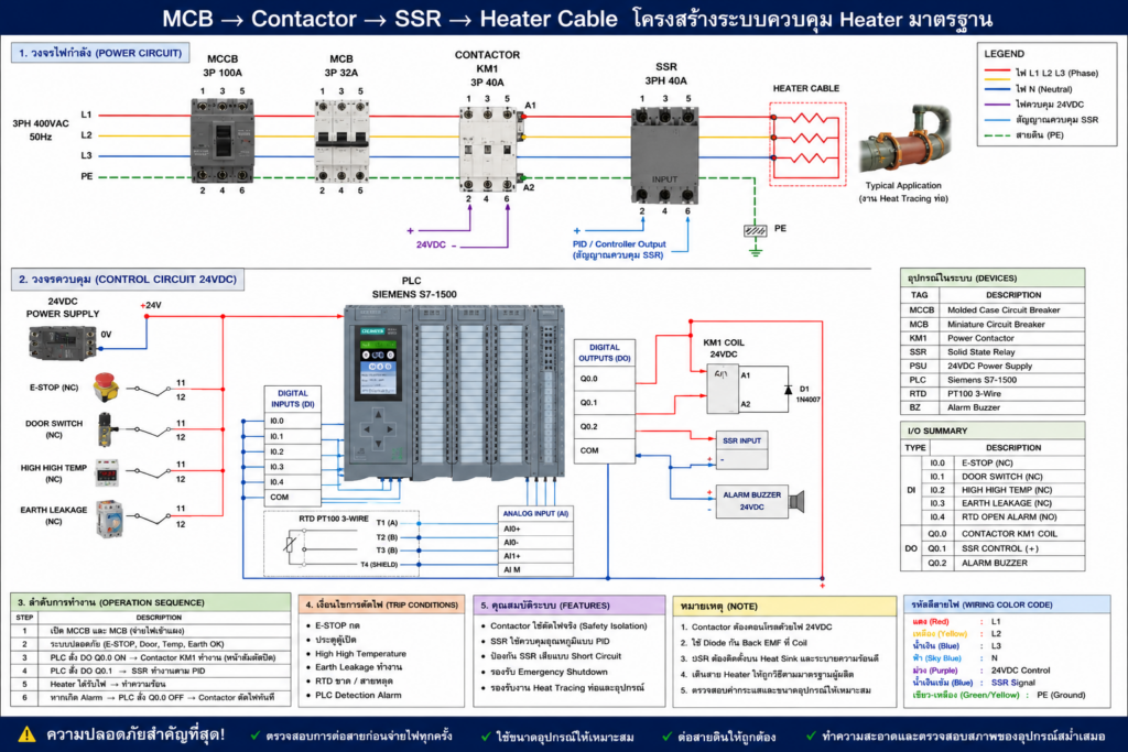
MCB → Contactor → SSR → Heater Cable
Standard Architecture for Industrial Electric Heat Tracing (EHT) Systems
1. Introduction
In industrial Electric Heat Tracing (EHT) systems, heater cables are used to maintain or increase the temperature of pipelines, tanks, and process equipment.
A reliable EHT control panel must provide:
- Safe power isolation
- Accurate temperature control
- Protection against SSR failure
- Emergency shutdown capability
For this reason, industrial EHT systems commonly use the following architecture:
MCB → Contactor → SSR → Heater CableThis design combines the advantages of:
- Mechanical isolation (Contactor)
- Accurate PID control (SSR)
2. System Architecture
The standard heater power path is:
Incoming Power
      ↓
MCB
      ↓
Contactor
      ↓
SSR
      ↓
Heater Cable
Each device has a different function.
3.MCB (Miniature Circuit Breaker)
The MCB provides:
- Short-circuit protection
- Overcurrent protection
- Branch circuit isolation
If excessive current occurs, the MCB trips and disconnects power from the heater circuit.
4.Contactor (Safety Isolation)
The contactor is used for:
✅ Real power isolation
The contactor contains:
- Coil (24VDC or 230VAC)
- Mechanical contacts
When the coil is energized:
Contacts CLOSE
→ Power passes to SSR
When the coil is de-energized:
Contacts OPEN
→ Power is completely disconnected
Why is the Contactor Important?
SSR devices commonly fail in:
FAIL SHORT / FAIL ONThis means:
SSR OFF
but heater still energized
Therefore, the contactor is used as a:
✅ Safety shutdown device
5.SSR (Solid State Relay)
The SSR performs:
✅ PID temperature control
The SSR switches heater power rapidly according to PID logic.
Typical operation:
ON 5 sec
OFF 5 sec
or
50% outputThis method is called:
✅ Burst Firing / Time-Proportional Control
6. Heater Cable
The heater cable converts electrical energy into heat.
Applications include:
- Freeze protection
- Process temperature maintenance
- Tank heating
- Viscosity control
7. Normal Operation Sequence
STEP 1 — MCB ON
Power becomes available for the heater loop.
STEP 2 — Contactor ON
PLC energizes the contactor coil:
24VDC → CoilThe contactor closes.
STEP 3 — PID Control Active
The PLC or temperature controller sends signals to the SSR.
Example:
ON 10 sec
OFF 10 sec
STEP 4 — Heater Energized
The heater cable receives controlled power.
8.Safety Shutdown Operation
If any abnormal condition occurs:
- Emergency Stop
- High High Temperature
- Earth Leakage
- Door Open
- SSR Failure
the PLC removes power from the contactor coil:
Contactor OFFThe mechanical contacts open and:
✅ Real power is disconnected from the heater
even if the SSR is stuck ON.
9. Why Not Use SSR Alone?
Because SSR:
- Cannot provide true isolation
- Has leakage current
- Commonly fails short circuit
Therefore:
SSR OFF ≠ Safe IsolationIndustrial standards therefore require:
✅ Mechanical isolation device
such as:
- Contactor
- MCCB
- Disconnect switch
10. Why Not Use Contactor Alone?
Contactor switching is mechanical.
PID control requires frequent switching:
ON/OFF many times per minuteUsing only contactors would cause:
- Contact wear
- Arc generation
- Noise
- Short lifetime
SSR is therefore used for fast control switching.
11. Industrial EHT Philosophy
The standard industrial philosophy is:
| Device | Function |
|---|---|
| MCB | Protection |
| Contactor | Safety isolation |
| SSR | PID control |
| Heater | Heat generation |
12. Conclusion
The architecture:
MCB → Contactor → SSR → Heater Cableis widely used in industrial EHT systems because it combines:
✅ Safe isolation
✅ Accurate PID control
✅ Reliable heater operation
The contactor provides emergency power disconnection, while the SSR provides smooth temperature control using PID logic.
This architecture is commonly found in:
- Chromalox EHT panels
- Thermon systems
- Industrial process heating systems
- Pipeline heat tracing applications