How to Find Fault Location in MI Cable
Professional Techniques Used in Industrial Electric Heat Tracing Systems
Introduction
Mineral Insulated (MI) Cable is widely used in industrial Electric Heat Tracing (EHT) systems for applications such as:
- Oil & Gas
- Petrochemical
- Refineries
- Power Plants
- High-temperature process systems
MI cables are preferred because they offer:
- High temperature resistance
- Excellent durability
- Mechanical strength
- Suitability for hazardous areas
However, when a fault occurs, locating the damaged point can be difficult and time-consuming without proper testing methods.
In real industrial environments, professional EHT technicians commonly use:
- Megger testing
- Resistance measurement
- Thermal inspection
- Section isolation
- Current injection
- Burn-point techniques
to identify fault locations quickly and accurately.
This article explains practical field methods for locating faults in MI heating cables.
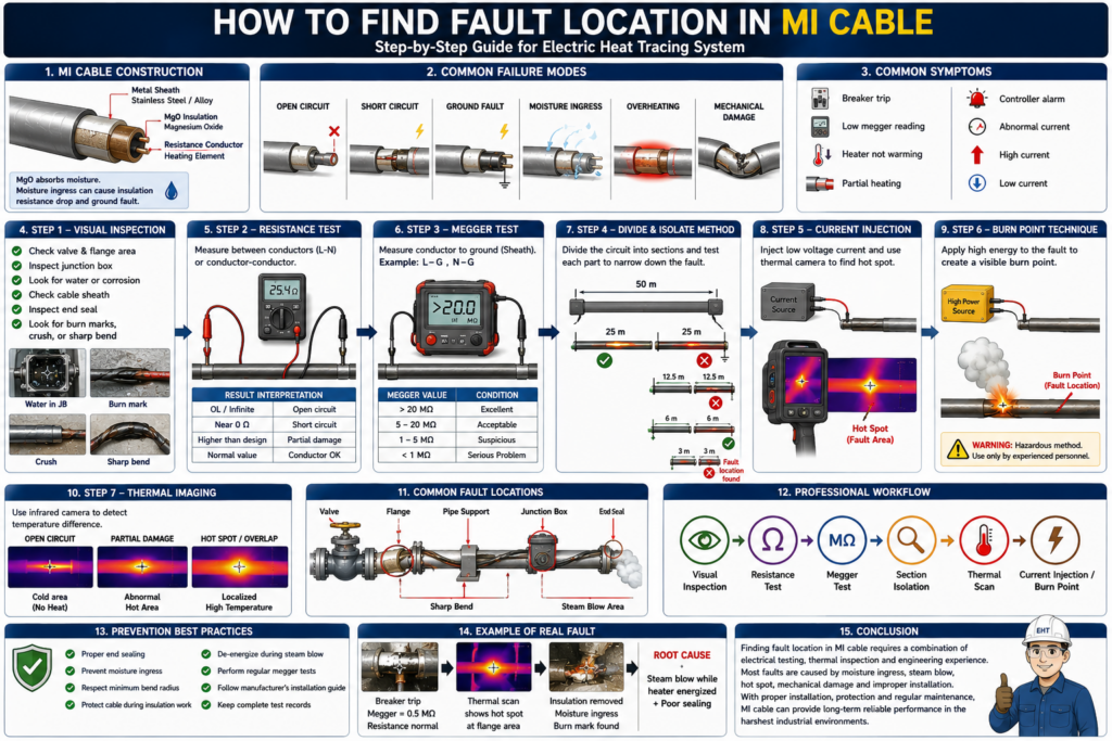
1. Understanding MI Cable Construction
Before fault finding, it is important to understand MI cable construction.
An MI cable typically consists of:
- Resistance conductor
- Magnesium Oxide (MgO) insulation
- Metallic sheath (Stainless Steel / Alloy)
MgO acts as both:
- Electrical insulation
- Thermal conductor
A critical characteristic of MgO is:
MgO absorbs moisture easily.When moisture enters the cable:
- Insulation resistance decreases
- Leakage current increases
- Ground faults may occur
- Breakers may trip
2. Typical MI Cable Failure Modes
Common failure types include:
| Failure Type | Description |
|---|---|
| Open Circuit | Broken conductor |
| Short Circuit | Conductors shorted together |
| Ground Fault | Conductor leakage to sheath |
| Moisture Ingress | Water absorbed into MgO |
| Thermal Damage | Overheating damage |
| Mechanical Damage | Crushing, bending, impact |
3. Initial Symptoms of MI Cable Failure
Typical symptoms include:
- Breaker tripping
- Low megger reading
- Heater not warming
- Partial heating
- Controller alarm
- Abnormally low current
- Abnormally high current
4. Step 1 — Visual Inspection
Always begin with a visual inspection.
Areas to Inspect
Valve and Flange Areas
These are high-risk locations because they act as heat sinks and hot spot zones.
Junction Boxes
Check for:
- Water ingress
- Moisture
- Carbon tracking
- Loose terminals
Cable Sheath
Inspect for:
- Burn marks
- Deformation
- Crushing
- Sharp bends
- Corrosion
End Seals
This is one of the most common failure points.
If the seal is damaged:
MgO will absorb moisture.5. Step 2 — Resistance Test
Measure conductor resistance.
Measure Between:
L-N
or
Conductor-to-Conductor
Then compare with design values.
Resistance Interpretation
| Result | Meaning |
|---|---|
| OL / Infinite | Open circuit |
| Near 0 Ω | Short circuit |
| Higher than design | Partial conductor damage |
| Stable normal value | Conductor likely healthy |
6. Step 3 — Megger Test
This is one of the most important tests.
Use a megger to measure:
Conductor → GroundExamples:
- L → Sheath
- N → Sheath
Typical Test Voltage
According to IEEE 515 and most manufacturers:
| Cable Type | Megger Voltage |
|---|---|
| MI Cable | 500 VDC or 1000 VDC |
Megger Value Interpretation
| Megger Value | Condition |
|---|---|
| > 20 MΩ | Excellent |
| 5–20 MΩ | Acceptable |
| 1–5 MΩ | Suspicious |
| < 1 MΩ | Serious problem |
7. Moisture vs Actual Cable Damage
For MI cables:
Low megger values do not always mean conductor failure.The problem may simply be:
- Moisture ingress
- Wet insulation
- Damp MgO
Real Example
Before insulation installation:
16 MΩAfter insulation installation:
0.7 MΩBut conductor resistance remained normal.
This indicates:
Moisture ingress rather than conductor damage.8. Step 4 — Divide and Isolate Method
This is a common refinery troubleshooting technique.
Principle
Divide the heating circuit into sections.
Example:
50 m
→ divided into
25 m + 25 m
Then perform megger testing on each section separately.
Procedure
If first half is normal
→ fault is in second half
If second half is normal
→ fault is in first half
Continue dividing:
25 m
→ 12.5 m
→ 6 m
→ 3 m
until the fault location is narrowed down.
9. Step 5 — Current Injection Technique
Used when the cable is not completely shorted.
Principle
Inject low voltage current into the conductor.
The fault location will generate more heat than surrounding areas.
Equipment Used
- Low-voltage current source
- Clamp meter
- Thermal camera
Detection Method
Scan the cable using a thermal camera.
The fault point typically appears as:
Localized hot spot10. Step 6 — Burn Point Technique
An advanced technique commonly used in refineries and petrochemical plants.
Used when:
- Fault resistance is high
- Fault location is difficult to identify
Principle
Apply temporary high energy to the fault.
This causes the damaged point to:
Become thermally visible.Then detect it using:
- Thermal camera
- IR thermometer
- Audio detection tools
WARNING
This method is hazardous and should only be performed by experienced personnel.
11. Step 7 — Thermal Imaging Inspection
One of the fastest fault detection methods.
Use:
Infrared Thermal CameraCommon Thermal Patterns
Open Circuit
After the break point:
No heat detectedPartial Damage
Some sections appear:
Abnormally hotOverlap / Hot Spot
Thermal image shows:
Localized high temperature area12. Common MI Cable Fault Locations
Typical failure locations include:
| Location | Common Cause |
|---|---|
| Valve | Hot spot |
| Flange | Overheating |
| Pipe Support | Crushing |
| Junction Box | Moisture |
| End Seal | Water ingress |
| Sharp Bend | Conductor damage |
| Steam Blow Area | Overexposure |
13. Steam Blow Damage in MI Cable
During commissioning:
Steam blowis one of the leading causes of failure.
Pipe temperatures may reach:
300–450°CIf this exceeds cable rating:
- MgO degrades
- Conductors oxidize
- Sheath becomes damaged
14. How Professionals Locate Faults Quickly
Professional EHT technicians usually follow this workflow:
Step 1
Visual inspection
Step 2
Resistance measurement
Step 3
Megger testing
Step 4
Section isolation
Step 5
Thermal scanning
Step 6
Current injection or burn-point testing (if required)
15. Prevention Best Practices
✔ Proper End Sealing
One of the most important requirements for MI cables.
✔ Prevent Moisture Ingress
Protect against:
- Junction box leaks
- Poor glands
- Damaged seals
✔ Respect Minimum Bend Radius
Avoid excessively tight bends.
✔ Protect Cable During Insulation Work
Mechanical damage during insulation installation is very common.
✔ De-energize During Steam Blow
Extremely important.
✔ Perform Regular Megger Testing
Recommended stages:
- Before installation
- After installation
- Before insulation
- After insulation
- Before energization
- During maintenance shutdown
16. Real Industrial Failure Example
Symptoms
- Breaker tripping
- Megger = 0.5 MΩ
- Conductor resistance normal
Investigation
Thermal scan revealed a hot spot near a flange.
After insulation removal:
- Moisture ingress observed
- Burn marks visible
- Evidence of steam blow overheating
Root Cause
Steam blow while heater remained energized
+
Poor weather sealing
17. Conclusion
Locating faults in MI heating cables requires a combination of:
- Electrical testing
- Thermal inspection
- Engineering experience
Common industrial troubleshooting methods include:
- Resistance testing
- Megger testing
- Section isolation
- Thermal imaging
- Current injection
- Burn-point techniques
Most MI cable failures are caused by:
- Moisture ingress
- Steam blow exposure
- Hot spots
- Mechanical damage
- Improper installation
The best prevention methods include:
- Proper installation
- High-quality moisture sealing
- Regular megger testing
- De-energizing during steam blow
- Monitoring thermal conditions during operation
When properly installed and maintained, MI heating cables can provide extremely long service life and reliable performance even in the harshest industrial environments.