SSR + PID Control in Electric Heat Tracing (EHT) Systems
1. Introduction
Electric Heat Tracing (EHT) systems are used to maintain the temperature of pipelines, tanks, and process equipment in industrial facilities such as:
- Oil & Gas
- Petrochemical plants
- Food processing industries
- Chemical plants
Heat tracing systems use electric heater cables installed along pipelines to maintain the required process temperature.
Modern EHT systems typically use the following control architecture:
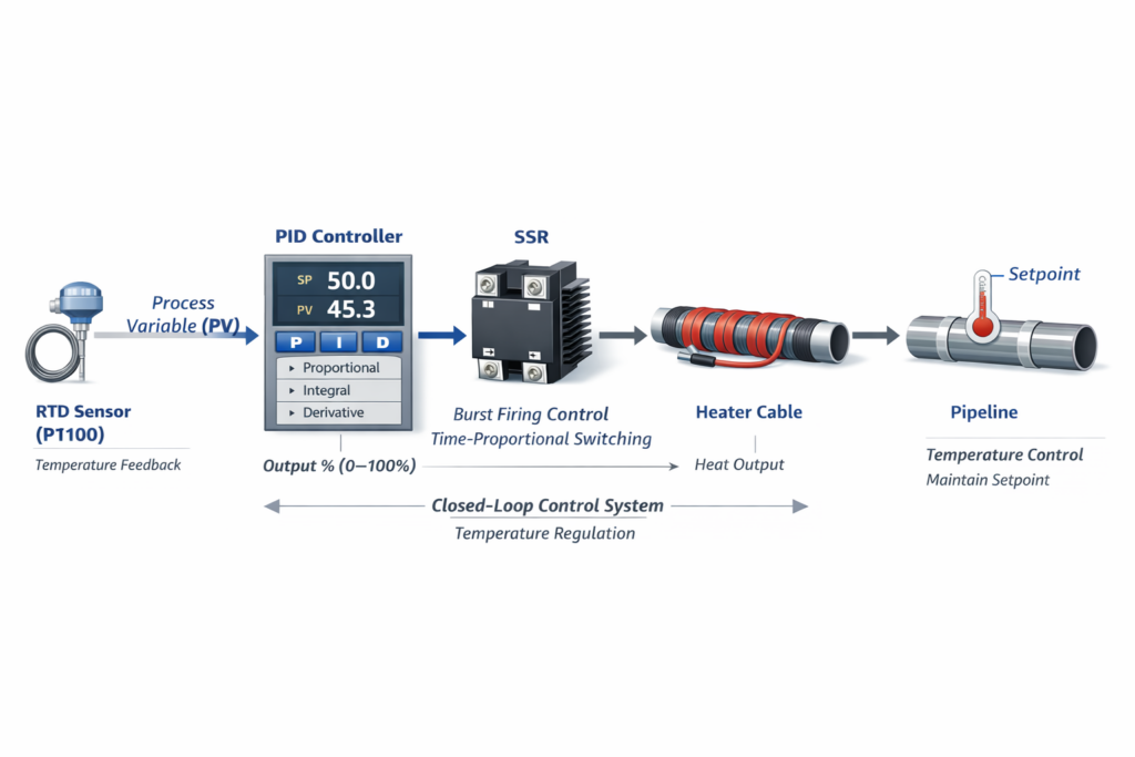
RTD + PLC + PID Control + SSR
This configuration provides accurate temperature control, reliability, and long equipment lifetime.
Typical system structure:
RTD PT100
     │
Temperature Transmitter
     │
PLC / PID Controller
     │
Digital Output
     │
Solid State Relay (SSR)
     │
Heater Cable
     │
Pipeline Temperature
Functions of each component:
| Component | Function |
|---|---|
| RTD PT100 | Measures pipeline temperature |
| PLC | Processes control logic |
| PID | Calculates required heating output |
| SSR | Switches electrical power to the heater |
| Heater cable | Generates heat |
What is an SSR?
A Solid State Relay (SSR) is an electronic switching device that replaces mechanical contacts with semiconductor components such as Triac or SCR.
Advantages of SSR:
- No mechanical contact wear
- Long service life
- Fast switching
- Silent operation
- Ideal for heater applications
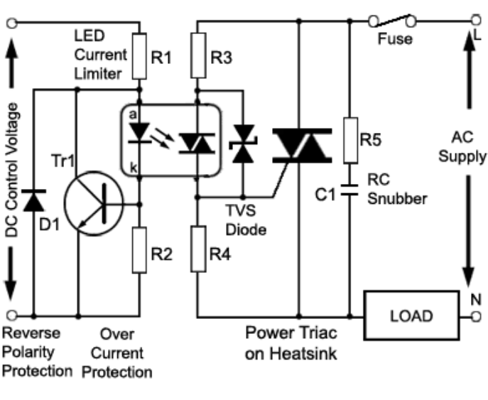
Internal Structure of SSR
Control Signal
      │
Optocoupler (Electrical Isolation)
      │
Triac / SCR
      │
AC Load (Heater)
Most SSRs also include a protection circuit:
RC Snubber
This circuit protects against voltage spikes but also causes a small leakage current, which explains why voltage may still be measurable when the SSR is OFF.
4. PID Control in EHT Systems
PID is a control algorithm used to regulate temperature.
Basic PID equation:
Output = P + I + D
Where:
| Term | Meaning |
|---|---|
| P | Proportional control |
| I | Integral control |
| D | Derivative control |
The controller calculates the heating output required:
0 – 100 %
Example Output Response
| Process Temperature | Output |
|---|---|
| 40°C | 100% |
| 45°C | 70% |
| 48°C | 40% |
| 50°C | 10% |
| 52°C | 0% |
5. How PID Controls the SSR
An SSR cannot reduce voltage level. It only has two states:
ON  = 220 VAC
OFF = 0 VAC
Therefore the PLC converts the PID output into a time-based switching control.
This method is known as:
Time Proportional Control
or Burst Firing Control
6. Burst Firing Control
Burst firing works by switching the heater ON and OFF in time intervals.
Example:
Cycle time = 20 seconds
Output = 50%
ON  10 seconds
OFF 10 seconds
Output = 25%
ON  5 seconds
OFF 15 seconds
Output = 75%
ON  15 seconds
OFF 5 seconds
The heater therefore receives average power proportional to the output percentage.
7. Voltage Waveform
Actual heater voltage:
220V ██████████        ██████████
     ██████████        ██████████0V            ██████████
              ██████████
When measured using a digital multimeter, the readings may fluctuate:
160 V
180 V
220 V
because the meter measures the average value of the switching waveform.
8. Why EHT Uses Burst Firing
Heater cables behave as thermal loads.
Key characteristics:
- High thermal inertia
- Slow temperature response
Therefore:
ON 10 seconds
OFF 10 seconds
does not cause noticeable temperature fluctuation.
Advantages:
| Advantage | Result |
|---|---|
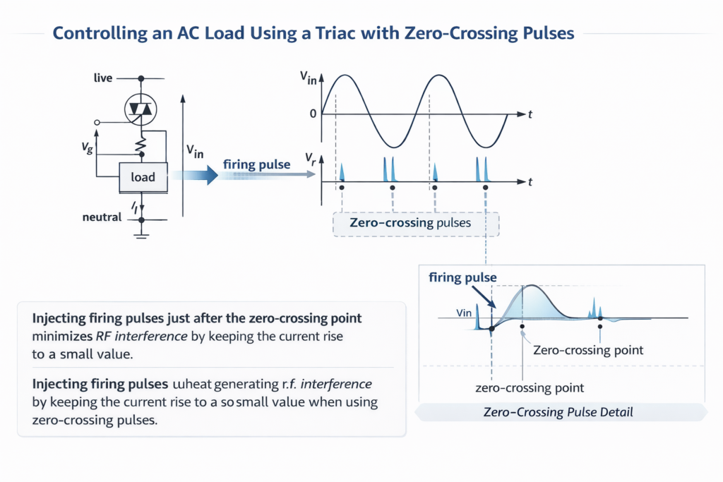
| Low EMI | No interference with PLC or instrumentation |
| Low harmonic distortion | Stable electrical system |
| Longer SSR lifetime | Fewer switching cycles |
9. Burst Firing vs Phase Angle Control
| Feature | Burst Firing | Phase Angle |
|---|---|---|
| Control method | Full cycles ON/OFF | Partial sine wave control |
| EMI | Low | High |
| Harmonics | Low | High |
| Typical use | Industrial heaters | Light dimmers |
| Used in EHT | Yes | Rare |
10. Common Issues in SSR + PID Systems
1. Voltage detected when SSR is OFF
Cause:
SSR leakage current
2. Unstable voltage readings
Cause:
Burst firing switching pattern
3. Frequent SSR failure
Common causes:
- Insufficient heat sink
- High operating temperature
- Heater inrush current
11. SSR Selection Guidelines for EHT
SSR current rating should typically be:
2 – 3 × heater current
Example:
Heater current = 12 A
Recommended SSR:
40 A SSR
Additional requirements:
Heat sink
Proper ventilation
12. Conclusion
The SSR + PID control system in Electric Heat Tracing operates according to the following sequence:
RTD → PLC → PID Calculation
           ↓
   Time Proportional Control
           ↓
          SSR
           ↓
      Heater Cable
           ↓
 Pipeline Temperature Stabilized
This control method provides:
- Accurate temperature control
- High reliability
- Long equipment lifetime
- Low electromagnetic interference
making it ideal for industrial heat tracing applications.