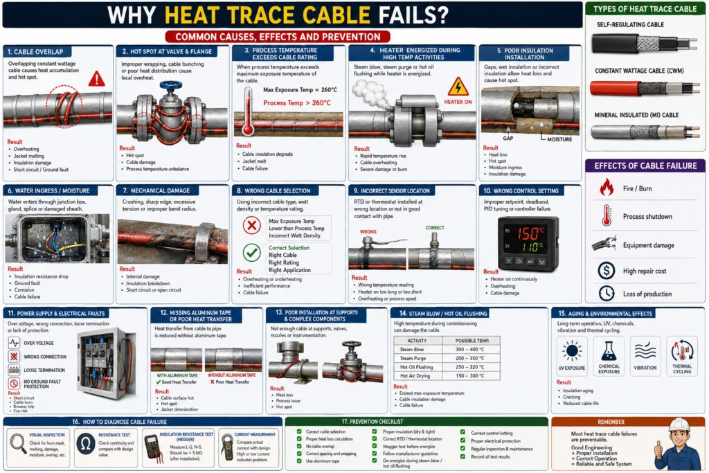
Why Heat Trace Cable Fails?
Common Causes of Electric Heat Trace Cable Failure
Introduction
Electric Heat Trace Cable is an essential component in industrial systems used to maintain the temperature of pipelines, valves, flanges, tanks, and process equipment. Its purpose is to prevent freezing, viscosity increase, crystallization, or process interruption caused by temperature loss.
Although heat trace cables are designed for harsh industrial environments, failures still occur frequently — especially during installation, commissioning, startup, and long-term operation.
In most cases, failures are not caused by manufacturing defects, but by improper:
- Design
- Installation
- Temperature control
- Commissioning practices
- Operational conditions
This article explains the most common causes of heat trace cable failure and how to prevent them.
1. Cable Overlap
One of the most common causes of failure is:
Cable overlapespecially with:
- Constant Wattage (CWM) cables
- Mineral Insulated (MI) cables
These cable types produce fixed heat output. When cables overlap, heat accumulates locally.
Example:
45 W/m cable overlapped in two layers
= localized heat density may become equivalent to 90 W/m
This causes:
- Hot spots
- Jacket melting
- Insulation degradation
- Low insulation resistance
- Cable burnout or conductor failure
Some self-regulating cables may tolerate limited overlap, but only if approved by the manufacturer.
2. Hot Spots at Valves and Flanges
Valves and flanges are among the highest-risk areas in any heat tracing system because they act as:
HEAT SINKSThis means:
Valves and flanges contain more metal mass
and lose significantly more heat than straight pipe.
Improper installation practices such as:
- Cable bunching
- Tight wrapping
- Uneven spacing
- Missing aluminum tape
- Poor insulation contact
can create uneven heat distribution.
Result:
Localized overheating
→ Hot spot formation
→ Cable failure
3. Process Temperature Exceeds Cable Rating
Every heat trace cable has temperature limitations, including:
- Maintain Temperature
- Operating Temperature
- Maximum Exposure Temperature
Example:
Max Exposure Temperature = 260°CIf the pipe temperature exceeds this value during operation or commissioning, the cable may be damaged even without overlap.
Typical high-temperature activities include:
- Steam blow
- Steam purge
- Hot oil flushing
- Hot air drying
- Process upset
- Startup overshoot
If the heater remains energized during these activities, failure risk increases dramatically.
4. Heater Energized During High-Temperature Commissioning
This is a very common issue in newly constructed plants.
During commissioning, operations such as:
Steam blow
Steam purge
Hot oil flushing
may occur while the heat tracing system is still energized.
In this condition, the cable receives heat from two sources simultaneously:
1. Process heat
2. Self-generated heater heat
As a result, cable surface temperature may exceed the manufacturer’s limit.
Consequences include:
- Jacket melting
- Insulation cracking
- Cable burnout
- Ground fault
- Breaker trip
Best practice:
De-energize and apply LOTO
before steam blow or hot oil flushing.
5. Poor Insulation Installation
Thermal insulation directly affects heat trace system performance.
Common insulation problems include:
- Insulation gaps
- Wet insulation
- Poor weatherproofing
- Damaged cladding
- Missing insulation around valves/flanges
- Air pockets beneath insulation
These issues create:
Uneven heat distributionSome areas become too cold while others accumulate excessive heat.
Wet insulation may also cause:
- Increased heat loss
- Corrosion under insulation (CUI)
- Insulation resistance drop
- Reduced cable life
6. Water Ingress and Moisture
Water and moisture are major enemies of heat trace systems.
Typical entry points include:
- Junction boxes
- Cable glands
- Power connection kits
- End seals
- Splice kits
- Damaged outer jackets
This issue is especially critical for MI cables because MgO insulation absorbs moisture easily.
Typical symptom:
Insulation Resistance decreasesExample:
20 MΩ → 2 MΩ → 0.7 MΩConsequences:
- Ground fault
- Leakage current
- Controller alarm
- Breaker trip
- Unsafe energization condition
7. Mechanical Damage
Heat trace cables can be damaged mechanically during installation or maintenance.
Examples include:
- Stepping on cable
- Excessive pulling force
- Over-tight cable ties
- Cable crushing
- Sharp metal edges
- Incorrect bend radius
- Installation near sharp supports or flanges
Some damage may not be immediately visible but appears after energization.
Typical symptoms:
- Local overheating
- Low megger reading
- Open circuit
- Ground fault
8. Wrong Heater Cable Selection
Incorrect cable selection is another major cause of failure.
Examples:
- Exposure temperature lower than actual process temperature
- Excessive watt density
- Using Constant Wattage where Self-Regulating is required
- Using Self-Regulating beyond temperature rating
- Wrong hazardous area approval
- Incorrect temperature classification
Example:
Actual process temperature = 300°C
Selected cable max exposure = 260°C
Result:
Cable damage during commissioning or operation9. Incorrect Thermostat or RTD Location
Sensor location significantly affects temperature control accuracy.
Incorrect RTD or thermostat placement includes:
- Too close to heater cable
- Located at abnormal hot spot
- Located at cold spot
- Installed outside insulation
- Poor pipe contact
This causes incorrect temperature reading.
Result:
Heater remains ON too long
or turns OFF too early
Excessive ON duration may overheat the cable.
10. Wrong Control Setting
Improper control settings can also damage the system.
Examples:
- Excessive setpoint
- Deadband too narrow
- Alarm failure
- SSR stuck ON
- Contactor welded
- Manual mode left active
- Improper PID tuning
Especially in SSR or PID systems, poor control may continuously energize the heater excessively.
11. Power Supply and Electrical Faults
Electrical problems are another common cause.
Examples include:
- Overvoltage
- Wrong wiring
- Incorrect L/N termination
- Short circuit
- Ground fault
- Incorrect breaker sizing
- Missing ground fault protection
- Loose termination
Consequences:
- Excessive current
- Overheating
- Sparking
- Cable damage
- Fire risk
12. Missing Aluminum Tape or Poor Heat Transfer
Aluminum tape improves heat transfer between the heater cable and pipe surface.
Without proper aluminum tape:
Heat transfer efficiency decreasesConsequences:
- Cable temperature rises
- Pipe receives less heat
- Hot spot formation
- Faster jacket degradation
This is especially important for:
- Constant Wattage cables
- Valve and flange areas
13. Poor Installation at Valves, Flanges, and Supports
High-risk areas include:
- Valves
- Flanges
- Pipe supports
- Shoe supports
- Nozzles
- Instrument connections
Common installation problems:
- Missing adders
- Cable bunching
- Excessively tight wrapping
- Cable contact with sharp edges
- Incomplete insulation
- Open insulation gaps
These conditions may cause:
- Excessive heat loss
- Local overheating
- Process instability
14. Steam Blow and Hot Oil Flushing Damage
In new plants, heat trace systems are often damaged during commissioning.
Major causes include:
Steam blow
Steam purge
Hot oil flushing
Typical temperatures:
| Activity | Possible Temperature |
|---|---|
| Steam Blow | 300–400°C |
| Steam Purge | 200–350°C |
| Hot Oil Flushing | 250–320°C |
| Hot Air Drying | 150–300°C |
If the cable maximum exposure rating is only 260°C and the heater is still energized, severe damage may occur.
15. Aging and Long-Term Degradation
Even properly installed cables eventually age.
Factors accelerating degradation include:
- Continuous high temperature
- UV exposure
- Chemical exposure
- Moisture
- Thermal cycling
- Mechanical vibration
- Poor maintenance
Typical aging symptoms:
- Gradual megger reduction
- Abnormal current
- Frequent alarms
- Inability to maintain temperature
- Random breaker trips
16. How to Diagnose Heat Trace Cable Failure
Step 1 — Visual Inspection
Check for:
- Burn marks
- Melting
- Wet insulation
- Mechanical damage
- Overlap
- Scratches
- Water inside junction box
Step 2 — Resistance Test
Measure:
L-N resistance
or conductor-to-conductor resistance
Typical interpretation:
- Near 0 Ω → short circuit
- OL → open circuit
- Abnormal value → conductor damage
Step 3 — Insulation Resistance Test
Use a Megger to measure:
L-Ground
N-Ground
Typical acceptable value:
≥ 5 MΩ after installation / maintenanceLower values require investigation before energizing.
Step 4 — Current Measurement
Compare actual current with design value.
High current may indicate:
- Short circuit
- Wrong connection
- Excessive cable length
- Overvoltage
Low current may indicate:
- Partial open circuit
- Loose connection
- Incomplete power supply
17. Prevention Checklist
Before energizing:
- Verify correct cable type
- Verify correct cable length
- Ensure no overlap
- Verify valve/flange adders
- Install aluminum tape properly
- Ensure dry and complete insulation
- Verify correct RTD location
- Perform megger testing
- Verify resistance values
- Verify controller settings
- De-energize during steam blow/hot oil flushing
- Maintain complete test records
18. Conclusion
Heat trace cable failures are commonly caused by:
Installation errors
Design mismatch
Commissioning activities
Moisture ingress
Temperature overexposure
Poor control systems
Particular attention should be given to:
- Cable overlap
- Hot spot formation
- Maximum exposure temperature
- Valve and flange installation
- Steam blow and hot oil flushing
The best prevention methods include:
- Proper cable selection
- Accurate heat loss calculation
- Correct installation practices
- Megger testing before and after insulation
- De-energizing during high-temperature activities
- Following IEEE 515 and manufacturer guidelines
When properly designed, installed, and maintained, Electric Heat Trace systems can operate safely, efficiently, and reliably for many years.