Valve and Flange Heat Trace Design in Electric Heat Tracing Systems
Introduction
In Electric Heat Tracing (EHT) systems, one of the most critical and frequently misunderstood areas is the design of heat tracing around:
- Valves
- Flanges
- Pipe supports
- Pumps
- Instruments
- Nozzles
These components behave differently from straight pipe sections because they act as:
HEAT SINKSIf not designed properly, they can cause:
- Excessive heat loss
- Process temperature drop
- Heater cable overheating
- Hot spots
- Thermal runaway
- Heater cable melting
This article explains the engineering principles behind Valve and Flange Heat Trace Design, including:
- Heat Sink behavior
- Adder calculation
- Wrapping methods
- Hot spot prevention
- Overlap risks
- IEEE 515 installation practices
1. Why Valves and Flanges Are Critical
Heat Sink Effect
Compared to straight pipe, valves and flanges contain:
- More metal mass
- Larger surface area
- Higher thermal inertia
As a result:
Heat loss at valves and flanges
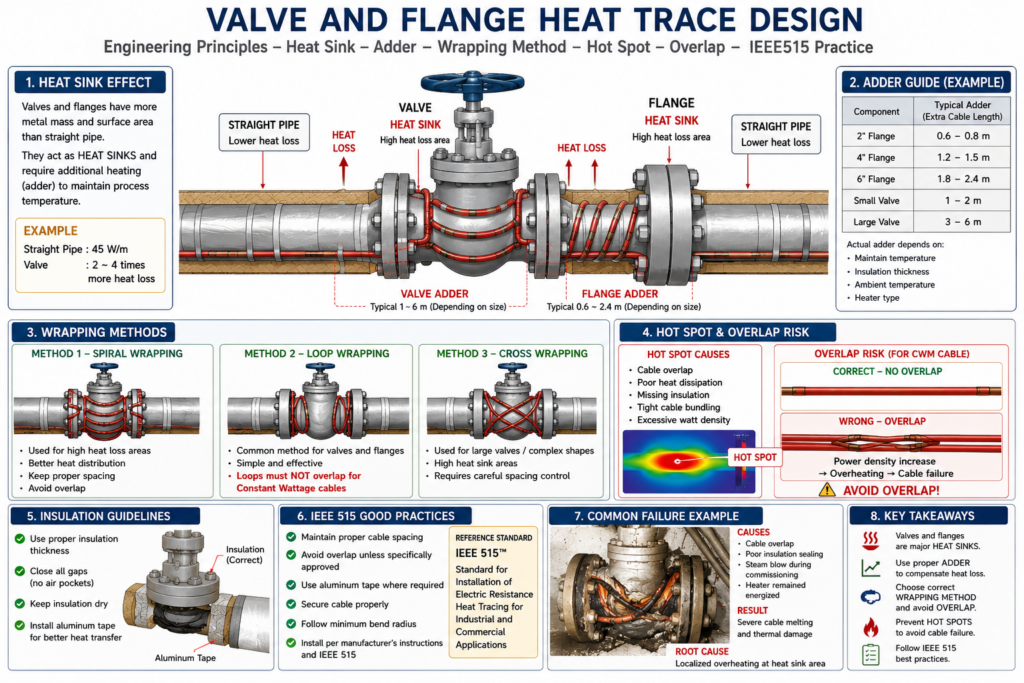
is significantly higher than straight pipe.Example
A 4-inch straight pipe may require:
45 W/mHowever, the same 4-inch valve may require:
2–4 times more heating energydepending on:
- Valve type
- Flange thickness
- Ambient temperature
- Insulation quality
- Wind exposure
2. What is an Adder?
Definition
An:
Adderis the additional heater cable length added around:
- Valves
- Flanges
- Supports
- Instruments
to compensate for increased heat loss.
Why Adders Are Necessary
If only straight pipe heat loss is considered:
Valve temperature may drop below process requirement.This can result in:
- Wax formation
- Product solidification
- Increased viscosity
- Process blockage
3. Typical Valve and Flange Adders
Example Guideline
| Component | Typical Adder |
|---|---|
| 2″ Flange | 0.6–0.8 m |
| 4″ Flange | 1.2–1.5 m |
| 6″ Flange | 1.8–2.4 m |
| Small Valve | 1–2 m |
| Large Valve | 3–6 m |
Actual values depend on:
- Maintain temperature
- Insulation thickness
- Ambient temperature
- Heater type
4. Wrapping Methods Around Valves and Flanges
Straight Pipe Installation
On straight pipe:
Cable is usually installed linearly.However, around valves and flanges:
Additional wrapping is required.5. Common Wrapping Methods
Method 1 — Spiral Wrapping
Used when:
- Heat loss is high
- Additional watt density is required
Advantages:
- Better heat distribution
- Increased contact area
Risk:
Incorrect spacing may cause overheating.Method 2 — Loop Wrapping
Common for valves and flanges.
Cable forms loops around the body of the valve.
Advantages:
- Simple installation
- Better heat concentration
Important:
Loops must NOT overlap for Constant Wattage cables.Method 3 — Cross Wrapping
Used for:
- Large valves
- Complex geometry
- High heat sink areas
Requires careful spacing control.
6. Hot Spot Formation
What is a Hot Spot?
A:
Hot Spotis a localized area where temperature becomes excessively high.
Common causes:
- Cable overlap
- Poor heat dissipation
- Missing insulation
- Tight cable bundling
- Excessive watt density
7. Why Constant Wattage (CWM) Cables Are Vulnerable
Constant Wattage cables produce fixed power output.
Example:
45 W/mIf overlapped:
45 + 45 = 90 W/mThis creates:
Localized overheatingwhich may lead to:
- Jacket melting
- Insulation degradation
- Thermal runaway
- Cable failure
8. Overlap Risk
Self-Regulating vs Constant Wattage
| Cable Type | Overlap Allowed |
|---|---|
| Self-Regulating | Limited overlap possible |
| Constant Wattage | NOT recommended |
| MI Cable | Strictly prohibited |
Why Overlap Is Dangerous
Overlap causes:
Power density increaseHeat cannot dissipate properly.
This is especially dangerous at:
- Valve necks
- Flange edges
- Pipe supports
- Insulated cavities
9. Valve and Flange Insulation
Proper insulation is critical.
Without insulation:
Heat loss increases dramatically.Common Insulation Mistakes
Missing insulation gap closure
Creates:
Air pocket → heat accumulation → hot spotWet insulation
Causes:
- Increased heat loss
- Corrosion under insulation (CUI)
- Thermal instability
Poor aluminum tape installation
Reduces:
Heat transfer efficiency10. IEEE 515 Good Practices
According to IEEE 515 principles:
Recommended Practices
✔ Maintain proper cable spacing
Avoid excessive concentration of heat.
✔ Avoid overlap unless specifically approved
Especially for:
- Constant Wattage cable
- MI cable
✔ Use aluminum tape where required
Benefits:
- Improves heat transfer
- Reduces hot spots
- Improves temperature uniformity
✔ Secure cable properly
Avoid:
- Crushing
- Sharp bending
- Excessive tension
✔ Follow minimum bend radius
Prevent internal damage to heater cable.
11. Real Field Failure Example
A Constant Wattage heater cable was installed around a valve.
Problems observed:
- Cable overlap at flange area
- Poor insulation sealing
- Steam purge during commissioning
- Heater remained energized
Result:
Severe cable melting and thermal damageRoot cause:
Localized overheating at valve heat sink area12. Engineering Design Recommendations
For Reliable Valve and Flange Heating
✔ Use proper adder values
Do not estimate visually.
✔ Distribute cable evenly
Avoid concentrated loops.
✔ Verify maximum exposure temperature
Especially during:
- Steam blow
- Hot oil flushing
- Commissioning
✔ Use thermostatic control
Prevent excessive surface temperature.
✔ Inspect insulation quality carefully
Proper insulation is essential for stable heat distribution.
13. Conclusion
Valves and flanges are among the most critical areas in Electric Heat Tracing systems because they behave as:
Major Heat SinksSuccessful design requires understanding:
- Heat loss behavior
- Adder calculation
- Proper wrapping methods
- Hot spot prevention
- Overlap risks
- Installation best practices
Improper installation around valves and flanges is one of the leading causes of:
- Heater cable overheating
- Thermal runaway
- Cable melting
- Premature failure
Following good engineering practices and IEEE 515 guidelines significantly improves:
- System reliability
- Temperature stability
- Heater cable lifetime
- Process safety
Proper Valve and Flange Heat Trace Design is not only an installation issue — it is a critical engineering discipline in every industrial heat tracing system.